Post by Bayley Wilmoth.—Radio frequency identification (RFID) systems are frequently used in connection with passive integrated transponders (PIT Tags), and the RFID receivers or antennas traditionally act as stationary pilings that are placed within a watershed so that scientists can track the movements of fish. However, it is possible for fisheries managers to further utilize this technology to estimate stocking exploitation and refine resource allocations. The system just needs to be mobilized and antennas must be designed to 1) efficiently be pulled through the water column while 2) maximizing the sampling area or read range. Dr. Colvin and I have been working towards developing an antenna design that can accomplish both objectives.
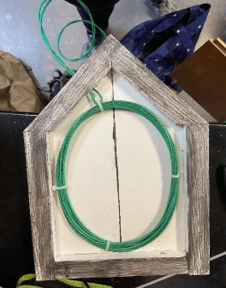
The first design that we came up with was far from perfect; yet, it taught us a lot. It is a hexagon shaped antenna made of PVC boards that are glued together. It has been weighted down at the bottom-most corner to ensure proper standing while in the water.

Between the boards is a coil of wires that have been fine tuned to work with the RFID mainframe.

This antenna was made in duplicate in order to pull the two antennas parallel to each-other on either side of our barge and maximize the water area that was being sampled at one time without double sampling the area within the two antennas.

While this antenna was sufficient at scanning PIT tags at the beginning of our trials, a shortage occurred that makes its read range vary dramatically or cease functioning all together making this design an unviable option for future field applications. Because the PVC boards were sealed with glue, the wire coils could not be accessed for inspection or replacement. The antennas are also only capable of scanning the water horizontal to them within the water column which makes the process of sampling the entire water column extremely difficult.

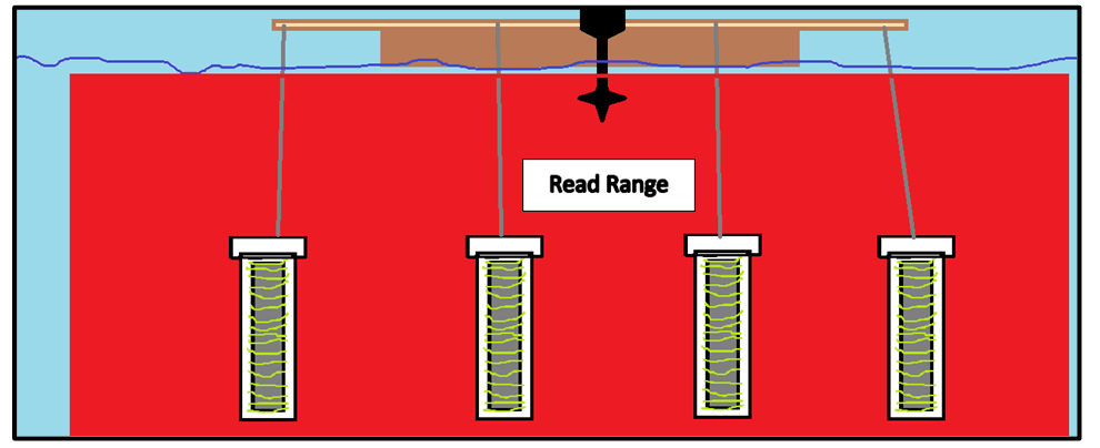
Now that we have a better understanding of potential challenges we could run into (i.e. shortages and struggling to sample the entire water column) and still know that our ability to pull the antennas through the water without snags is important, it is time to brainstorm new designs again. So, here is a step by step layout of what we are proposing:
1) Take a 1-inch PVC pipe, fill it with concrete in order to ensure the antenna sinks without interrupting its ability to work by attaching metal. 2) Coil antenna wires around the PVC and tune the coil to work with the RFID mainframe. By utilizing the cylindrical shape of the PVC, we are now able to scan on all sides of the antenna. 3) Place the concrete filled, wire coiled PVC within a 2-inch PVC pipe and cap it for protection when submerged; thus, eliminating room for unfixable shortages by always allowing wire access through cap removal if need be. 4) Repeat four times. 5) Attach all four antennas to the RFID mainframe and submerge them behind the boat. 6) Reliably estimate how many tagged fish are in the water body!
